19+ Start Stop Circuit Wiring
Web A start-stop wiring diagram is a schematic representation of the electrical connections and components used in a basic start-stop circuit. Depressing the START button maintains the circuit.
Chevy Silverado And Gmc Sierra Forum
The 3 Wire StartStop control circuit is the most common electrical diagram that you will need to.
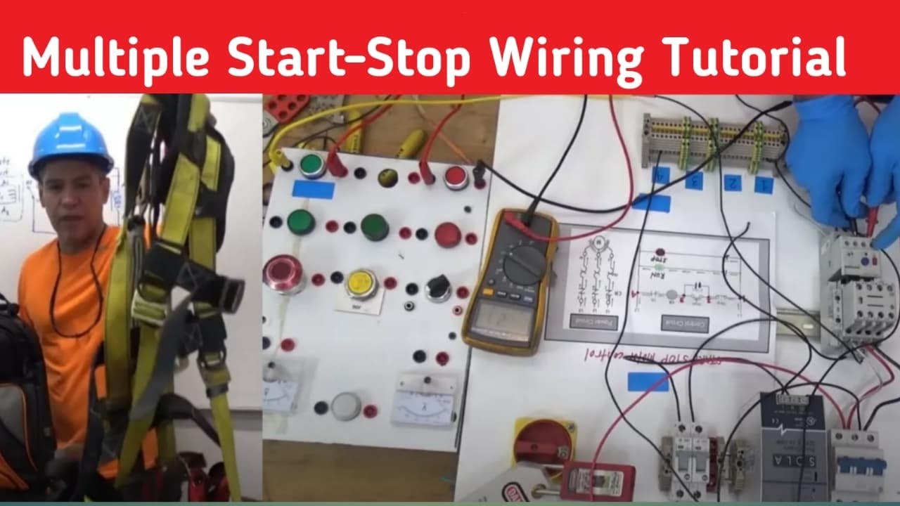
. Web How to Wire a Start Stop Motor Control 3 Wire Circuit. Web 33K subscribers. 2 4 6 M 1 OL 3-Phase Motor A1 A2 Remove Wire C when it is supplied.
This way pressing the. 182K views 5 years ago Electrical Troubleshooting. Advantages and disadvantages of the.
A 2-wire circuit is intended for one signal to run a function and if that signal is removed the function stops. In some cases it might be necessary to start a motor-controlled device using a push-button switch but allow another control to turn it off. Required Electrical Supply for the Starting.
Techniques to Control Start-Stop circuit wiring. The 3-wire start-stop circuit is typically used to remotely start and stop large industrial motors. What is the 3-wire start-stop circuit.
The electrical supply required for a start-stop circuit depends on the voltage rating of the. If the hood of the car is open when you start the car the AutoStop-Start is disabled even if you close the hood with the car still running. How does the Start-Stop Circuit Work.
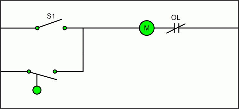
Web In general the start button should be wired in parallel with a motor control circuit while the stop button should be wired in series with the power supply. Web APDahlen February 27 2024 828pm 1. L-m----e- 1 The START button mechanically maintains the contacts that take the place of hold-in contacts.
Web Craig Michaud- Electrical Instructor. Web 2-Wire Control 3-Wire Control Start Stop 3 2 1 1 3 Not for use with Auto Reset OL Relays. Theyre generally critical in machine control.
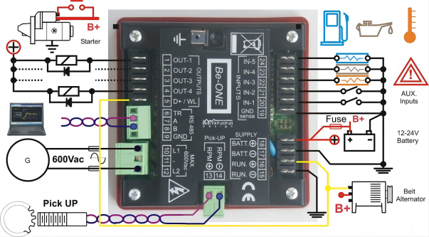
Web The wiring diagram for a start-stop control circuit provides a visual representation of how the electrical components are connected to each other and to the motor. What power supply does the start-stop circuit need. Web A start stop schematic diagram is a graphical representation of the electrical circuit used to control the start and stop operation of electric motors or other devices.
As long as you follow the ladder diagram and. Web In this article we will learn about stop start contactor wiring diagram 3 circuits for controlling three phase motor. Web 2-Wire Start-Stop Circuit Wiring.
This type of wiring diagram is commonly. This is different from. When the state switch is open the motor will not.
Web A start-stop circuit is an electrical circuit that starts or stops electrical components including motors or ladder logic networks. This video is a step by step explanation of wiring Start Stop basics. Method 1 - 2.
Web 1 Oct 18 2019 Edited How it Works. Web Start by identifying the components that need to be included in the wiring diagram such as the start-stop switch power supply motor and any additional devices or. This diagram is the most basic circuit that uses a switch to control a motor through a contactor.
Web Two-Wire and Push-Button Control.

Youtube

Pinterest
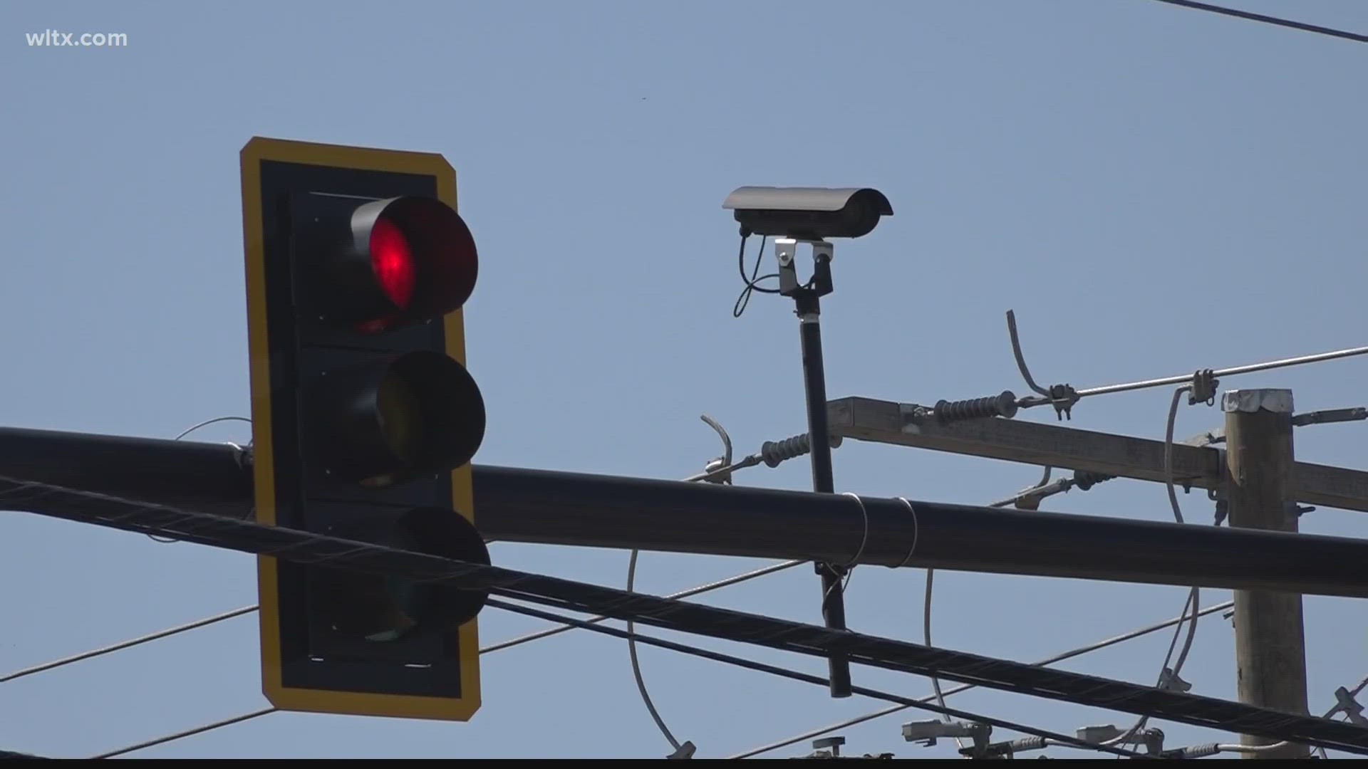
Wltx
Subaru Forester Owners Forum

Youtube
Diy Home Improvement Forum
1
Jhdpcb
Ijdmtoy Com

Bccampus Pressbooks

Suma Performance
Nextpcb
Youtube

Yumpu
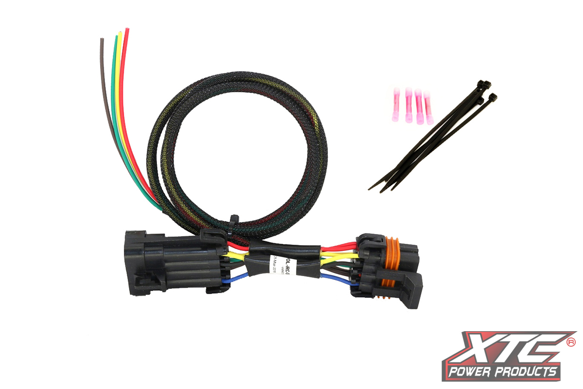
Xtc Power Products
Nextpcb

Pinterest